SEM (Solid Ejection Material) Shocks a New Crash Safety Technology with Applications in Every Field of Transportation
Steve Knotts , United States The SEM shock technology is a completely new method for absorbing the crash energies from all type of vehicle crashes (e.g. cars, trucks, trains, aircraft, ships) plus there are a number of military and Homeland Security applications (e.g. military vehicle airdrop platforms, blast armor, truck barriers to prevent terrorist vehicle entry). The large number of application markets for the SEM technology is actually quite exciting, plus the fact that SEM systems will reduce injuries and save lives, in numerous transportation and security markets, adds another level of great importance to the technology. Another interesting point regards the existence of competing technologies, whereas, as far as we know, there currently aren’t any.
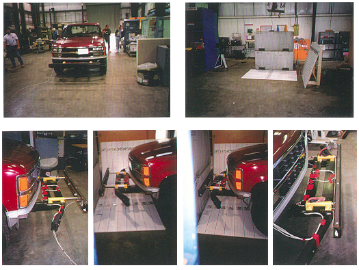
 Basically SEM shocks use the same high pressures that are present in the injection molding process of plastic parts. Depending on the plastic type and the geometry of the mold, the injection pressures can range from 2,500 psi up to an incredible 35,000 psi! SEM shocks use these same high flow pressures to restrain the piston assembly, on a range of SEM shock types. The nice thing about these high flow pressures is the fact that relatively small parts can still deliver extremely high restraint loads. For instance, just 2 SEM shocks with a 1.0” ID (Inside Diameter) and 7.0” of available travel, stopped a full size, 5,400 lbs Chevy pickup which was moving at 7.5 mph! That’s 50% more Kinetic Energy (KE) than the standard 6 mph collision speed which the world’s Auto Manufactures and world’s Test Facilities normally use. To give you an idea of the stopping power, just 2 pieces of fiber fill rubber that were slightly larger than the typical cigar, absorbed enough KE, from that 7.5 mph impact, to prevent at least $5,000 of damage that surely would have been delivered to our full sized Chevy test truck.
As an extreme example of the stopping power of SEM systems, consider a ship hitting a dock. The SEMISAS Company is located in the Seattle area and on occasion a Washington State Ferry looses power, which prevents the activation of the reverse thrust, so the Ferry Boat just “glides” into the dock. The Ferry’s velocity is relatively slow but with all of its mass, it still has a great deal of momentum. Therefore the damages to the dock structures are normally expensive (e.g. many times it can be in the millions of dollars). So what size SEM shock housing would be needed, to stop that runaway Ferry? As a rough calculation consider a 10,000 ton ship, moving at 10 mph and hitting an SEM shock with 10.0’ of available travel. Surprisingly, a single SEM shock would only need to have a 20.0” ID to bring that ship to rest (e.g. assumes a 20,000 psi ejection pressure).
As pointed out earlier, there are many applications for the SEM technology and while some of these applications may already have a “solution” for the crash energy absorption, most of these “solutions” are at least a hundred years old and many of these methods didn’t work well then (100 years ago) nor do they work well now. As a challenge to your members, try to find a road barrier design, or a vehicle bumper shock, etc.; that doesn’t use some form of metal or maybe plastic, that is undergoing bending, crushing or buckling, as the primary energy absorption method. The problem with some of these methods, namely buckling, is, they are not very controllable. Some of the loads in a buckling structure can vary by 50% or more (e.g. consider an aluminum can that might fail under a 30 lbs load but the next aluminum can, that’s exactly the same, may fail under a 35 lbs load). So buckling behavior is a poor method for crash energy absorption but even though buckling behavior really can’t be controlled, a lot of industries (e.g. auto industry, highway barriers, trains) still use buckling structures as the primary crash energy absorption method. Compare this now to an SEM shock set which is capable of supplying the desired restraint load performance within 1% or less, of the design load, and be able to deliver such a controlled performance every time and at any temperature and in any environment. If the auto industry started using SEM shock systems they would undoubtedly score a lot higher in IIHS (Insurance Institute for Highway Safety) crash tests.
It’s interesting that there are essentially 3 areas of auto safety that the auto industry should focus on, but there are really only 2 that are rigorously explored. For instance, Auto Engineers attempt to make “smart” systems to control the braking (e.g. anti-skid, collision avoidance braking) and/or controlled traction during a rigorous maneuver, both of these control types are an attempt to prevent a collision. The second safety area is the use of the airbag systems, to cushion the passengers during a severe crash event. But the 3rd area that normally seems to be “off-the-radar-screen” for the Auto Industry, is the actual crash energy absorption performance of the vehicle body. It appears that the current Auto Designers assume the only option is to use crushing and buckling metal as the primary energy absorption method, and since this method is not very controllable; why try to improve it? So instead it’s just explored & improved to a low level and then essentially ignored. Well if SEM shock systems are employed in the vehicle bumper and frames, the Auto Designers will have a completely new tool to control the crash loading and energy absorption performance of the vehicle body, so now this 3rd safety area can be given the same consideration as the other 2.
I probably inherited my interest in design and innovation from both sides of my family. My father was a Navy Captain and submarine commander. My Father did everything from car repairs at home, to save a little money; to being an active participant in the Polaris missile program. My Mother’s Father was a Navy Rear Admiral and the first CO of the Point Mugu missile test facility. My Grandfather dabble in the design and construction of a number of gadgets while he grew up (e.g. prop driven 3 wheel car, 300 ft radio antenna tower), plus he had a number of Patents and some consider him to be the father of the guided missile (https://www.usna.com/SSLPage.aspx?pid=2655). So I guess I inherited some of my interest in design from both sides of the family.
As a kid I constructed the typical tree forts and un-powered and powered go-carts. As I got older (e.g. high school) I constructed steel bumpers for the old Dodge Powerwagon, plus I built 2 utility trailers to transport firewood (e.g. 2nd trailer was a tandem axle trailer which was capable of hauling 2 full cords of firewood). I also got involved in some more industrious projects…
• Little Cabin in Okanogan Forest – Some friends and I built a little cabin on some Okanogan Forest land in Eastern Washington. The cabin was build with timber that was taken from the land. It was a 3 story A-Frame with a 20.0’ x 20.0’ main room and a 10.0’ x 20.0’ front deck. There was also a natural spring on the land on a hillside with about a 100’ elevation. We built a cistern and piped the water down to the cabin and got about 50 psi water pressure. As to the timber, one of the trees that the sawmill owner fell was a 129 ft yellow pine and that tree literally cleared a road when it fell. Ron had a duel axle semi, with a hydraulic crane, to lift and transport the timber but he didn’t have a log skidder and he wasn’t going to use his semi anymore because he had damaged the differentials when he skidded timber in the past. So the next morning, my friend Rich and I decided to skid the timber out with my old Dodge Powerwagon. With some doubled up nylon rope and the granny gears we manage to skid out all of the timber with most of the sections being 10.0 ft lengths. We told Ron that evening that we had some timber for him to pickup and he wondered how we skidded the timber to the road. We told him that we used the old Powerwagon. He didn’t believe us. The next morning Ron saw all of the timber skid out and he couldn’t believe it, since he said… “The butt end of that log had to weigh over 3 tons!”
• University of Washington Degree in Aeronautical and Astronautical Engineering – Never was the best student in terms of my test scores but I went to every class and actually learned something. During my time at the UW one of the interesting things that’s related to innovation, was a rotary engine design that I had. In my senior year I got the OK to build and research that rotary engine but I had to talk to the guys in the Aero Department’s Machine Shop. I showed my drawings to a German Machinist (Ado) who ran the shop. Of course Ado wanted to know the tolerances on the parts (which we were never taught in any collage classes). Also, the design was complex enough to where Ado wanted to think about it. The next day Ado told me that he didn’t see how any of his team could build the parts and if they could build the parts, it would probably take one of his machinists at least 6 months to build it. Of course I was disappointed but I mentioned that I was able to make a very rough prototype on a drill press at home. This perked Ado’s interest and he wanted to see my prototype. The next day I brought in my very crude prototype and Ado was so impress, with my little piece of junk, that he decided they could build a “good” prototype in their shop.
• U.S. Navy – After graduating from the UW, I joined the Navy’s Aviation Officer Candidate School (AOCS), in Pensacola, FL. The AOCS booth camp was an interesting experience because in the first week of “training” our wakeup call was a Marine Drill Instructor who kicked a garbage can down the hall at 4:30 am. Since I never had a good memory, I didn’t do very well in the standard classes (e.g. military admin, military law, etc.) but being an Aero Engineer I aced the aero exam and did well in the engines and navigations course. This left many scratching their heads because it was normally the other way around. I went on to Navy Flight Training in Corpus Christi, TX where I flew the T-28 trainer, with its 1,425 hp engine that supposedly could beat any aircraft in the Navy’s inventory to 5,000’. I started my flight training with a Marine flight instructor, Capt. Drake, who was a darn good instructor but since they were decommissioning the T-28 most of the student pilots got bounced around to more than one instructor. Since it is difficult to adapt to different instructors and again, not having the best memory, all resulted in me washing out of the flight training about half way through primary training. And since at that particular time (e.g. early 1980’s), the Navy was doing fine in terms of their manpower, so they released me to the private sector.
• Boeing Aerospace Co. - Within about a year I got a job with Boeing as a Design Engineer on a Navy missile program. In the 7 years I spent at Boeing I was responsible for numerous part designs for the missile shell and I had the opportunity to participate in number of test efforts. From such tests I got a healthy respect for high Kinetic Energies. In one test an F-4 dropped a ballasted missile mockup, over a designated drop zone in Mohave desert. The parachute didn’t deploy and that mockup hit the desert at 450 kts plus. Needless to say the 14.5” diameter steel tube which was 0.50” thick was now essentially flat. Later our team did a drop of a nearly complete missile assembly with its payload being a ballasted Mk-50 torpedo. This time the F-4 was dropping the missile payload over water but again not all of the ordinance worked, so again no parachute was deployed. When we retrieved the Mk-50 torpedo, with its 2.0” thick stainless steel nose cone, there was a notable dent in the nose cone that was at least 0.50” deep and that dent was from the pressure generated when that nose cone impacted the water!
• Business After Boeing - I decided I needed to try to design some consumer products to try and generate capital for some of my more technical ideas. So I started the Paragrate company which designed a unique fire-grate that held firewood in a tall stack so that more radiant burning surface would be exposed to the living area. The other nice thing about the Paragrate was it was self feeding, so as the wood burned the stack would settle and always stay in close contact, so it wouldn’t go out. Also for the Paragrate company I designed a heavy duty and expandable log rack, for storing firewood. I was initially producing the product myself but in the very early stages I happen to locate a Taiwanese Company fireplace equipment manufacture and Geo Found Merchandise produce the Paragrate products for over 10 years. Our biggest customer was the Frontgate catalog but they dropped the expandable log rack and log rack covers back in 2003. Also in the 1990’s I came up with 4 U.S. Patents, two of which were for a new gear design (e.g. Bearing Tooth Gears) that use rotating gear teeth, to eliminate the sliding tooth contact and all of the problems associated with sliding contact (e.g. tooth size is limited for sliding contact gears; plus there is a range of failure times wear, pitting, scoring, for gear teeth in sliding contact). Also in the late 1990’s I got Patents for the SEM (Solid Ejection Material) shock technology, which is SEMISAS, LLC’s current focus (SEMISAS – Solid Ejection Material Impact Shock Attenuation Systems).
As previously mentioned the SEM (Solid Ejection Material) shock technology has a number of applications in every field of transportation and even though we currently don’t have any production contracts; the SEM technology has been through numerous test efforts, such as the following…
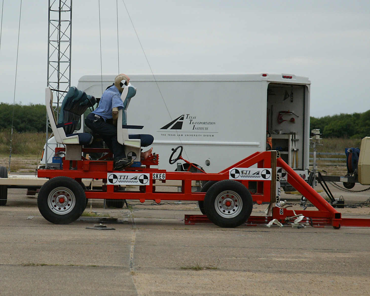
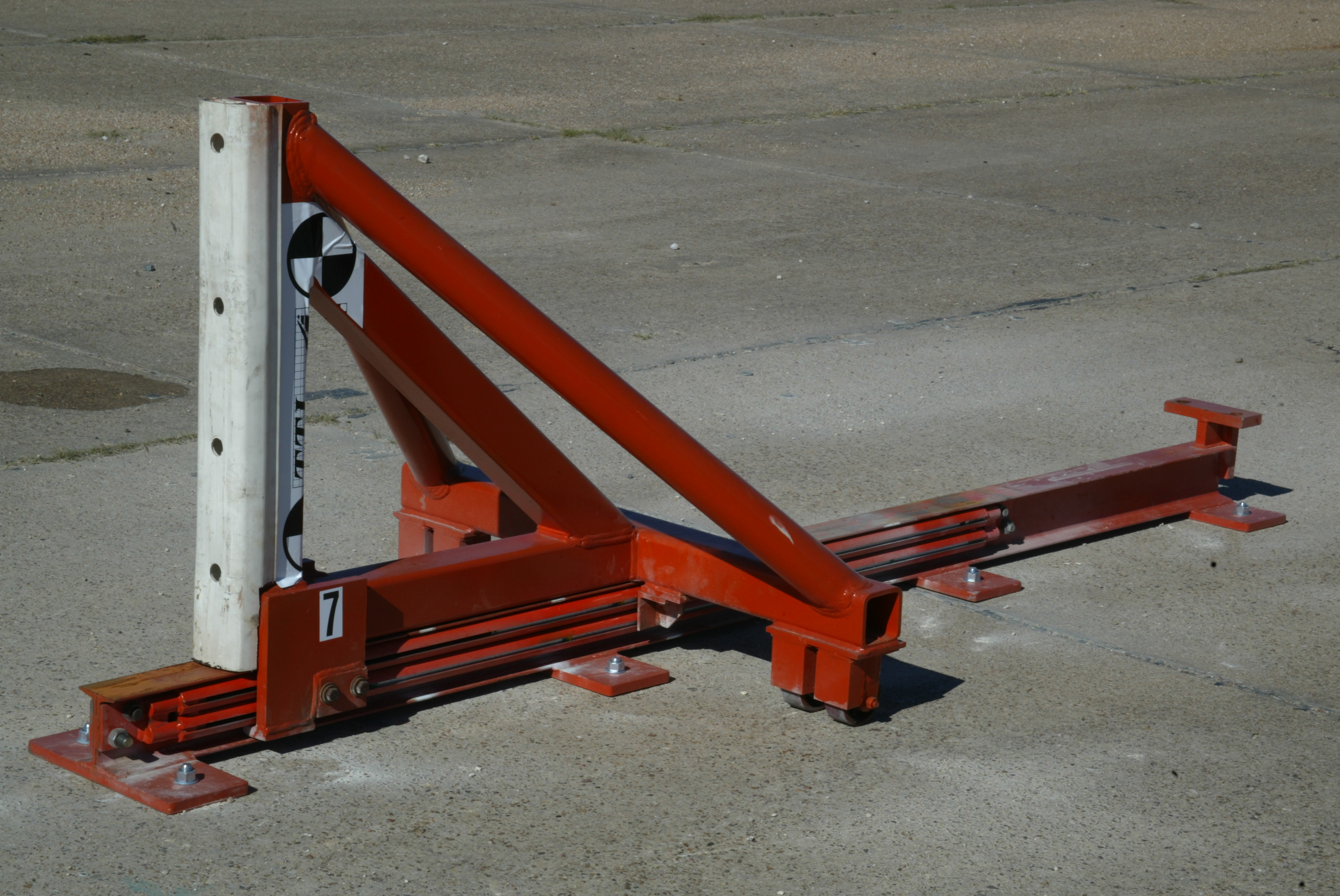
In Nov 2004 and in Nov 2005 a total of 9 impact tests were run at the Texas Transportation Institute (TTI) and both of the test efforts were funded by the National Academy of Sciences’ (NAS), Transportation Research Board’s (TRB) High Speed Rail-IDEA program. A technical report was released at the completion of the test effort (Crash Energy Absorption for High-Speed Rail Passenger Seats Using Solid Ejection Material). In this study the SEM technology was used in railcar passenger seats (which was the major goal of the study), but we also used SEM shocks in the impact barrier. These barrier shocks were designed to deliver a spec 8-g max by 250 ms triangular crash pulse to the 4,100 lbs Bogie test vehicle, which had the railcar test seats and test dummies mounted on it. Here’s the web address for that report (http://www.trb.org/studies/idea/finalreports/highspeedrail/hsr-45final_report.pdf).
For some more detailed information on some of our earlier test efforts, there’s was a 1999 report that was released by the Society of Engineers (SAE) which focuses on our earlier test efforts, such as a series of drop tests and a moderate speed vehicle impact test (http://www.sae.org/technical/papers/2001-01-3099 , Vehicle Crash Performance Augmentation Through SEM (Solid Ejection Material) Shock Isolation).
We’ve also posted some information regarding some of our test efforts on the YouTube website, so if your members would like to see some SEM shock systems in action, they can go to the following YouTube web addresses…
1. (http://www.youtube.com/watch?v=hSBO7dy0CYE) - Three short and slow motion film clips showing a 4,100 lbs Bogie test vehicle hitting an SEM impact barrier at 23.5 mph. Last clip shows a close-up view of the fiber wrapped elastomer cord being expelled from the SEM shock housings.
2. (http://www.youtube.com/watch?v=R9xPNrIvnLM) - A total of 7 impact tests were run on a full sized Chevy pickup, with a gross weight of 5,400 lbs. There was no structural damage other than the replacement costs of the SEM shocks (less than $100); and this is with impact speeds that ranged from 3.5 mph up to 7.5 mph!
3. (http://www.youtube.com/watch?v=sF3_Cc8G0zI) - The SEM technology was used in some railcar passenger seats to help reduce the injuries experienced by unbelted passengers. Also, in the same test effort SEM shocks were used in the vehicle impact barrier, to stop a 4,100 lb Bogie test vehicle which had an impact velocity of 23.5 mph. The video shows the last 3 impact tests that were run at TTI (Texas Transportation Institute).
4. (http://uk.youtube.com/watch?v=9upftsUtC24) - The highest impact speed tests to date used only one 1.25" ID SEM shock housing, with 15.0' of available travel. That single SEM shock assembly stopped a 1,700 lb Bogie vehicle, with a top impact speed of 62 mph.
As a closing thought and to give your members an idea of the performance potential for an SEM system, consider the test data from the 4th test effort listed above. The Highway Barrier company that conducted these high speed tests had a method for grading the performance of the crash barriers that they tested. Essentially they would calculate a ratio of the costs, to deliver a unit of energy absorption performance, or dollars per kilo-joule ($’s/KJ). It was inferred to me that they assumed the minimum $’s/KJ value, for existing road barrier systems, was about $0.50/KJ but the $’s/KJ values that they got in their SEM barrier tests were $0.12/KJ and $0.08/KJ.
So in summary, SEM systems can be tailored to deliver an exact energy absorption performance, per the design requirements; and be designed for an extremely wide range of applications; and deliver that performance for a lower cost than the majority (if not all) of the conventional energy absorption methods that the Design Engineers currently use today.
Next Story »