Structure Based Orientation Indication Device
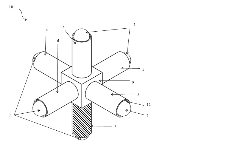
The report details an engineering art work of an indication device. The prime goal of this engineering work is to determine the orientation of the platform about pitch, roll and yaw axes. The indication device is known as Structure Based Orientation Indication Device (SBOID). The Structure Based Orientation Indication Device (SBOID) utilizes a simple construction to determine the orientation of the platform to which the Structure Based Orientation Indication Device (SBOID) is fixed ontoFigure 1 illustrates a perspective view of the rod structure (101) of the orientation indicating device (100) comprising a central cube structure (9).
The rod structure (101) is constructed in such a way that, one end of each of the rods (1, 2, 3, 4, 5 and 6) is fused to the center of one face each of the cube structure (9). The weight of the rod (1) is heavier than that of the other rods (2, 3, 4, 5 and 6). By providing a heavier rod (1), the center of gravity of the rod structure (101) is always acting at the tip end of the heavier rod (1) which always points towards gravity.
The heavier rod (1) (for the purpose of illustration is hatched as shown in Figure 1) pointing towards gravity with respect to the other rods (2, 3, 4, 5, 6). ). The heavier rod is manufactured such that, the amount of material used is greater in volume than that of the volume of material used in manufacturing other rods, thus making the heavier rod orient itself towards gravity during operation. In the device, the heavier rod (1) may be provided with a different color, when compared to the other rods to facilitate visual indication.
• All of the rods (1, 2, 3, 4, 5 and 6) are of equal lengths (L) from the tip end to each of the faces of the cube structure (9).
• The rods (1, 2, 3, 4, 5 and 6) have to be equal in length (L), otherwise, there would be imbalance forces acting on the rod structure (101) due to eccentricity developed at the center of gravity on the rod structure (101).
• The dimension of the plurality of rods (1, 2, 3, 4, 5 and 6) is equal.
• The plurality of rods are circular in shape and are having a diameter (D) which are consistent with each of the plurality of rods (1, 2, 3, 4, 5 and 6).
Further, each of the plurality of rods (1, 2, 3, 4, 5 and 6) can be configured in shape as circular, square, rectangular, triangular, trapezoidal, octagonal, or any other shape which is generally known.
The plurality of rods (1, 2, 3, 4, 5 and 6) are fused to the centre of one face each of the cube structure (9) in such a way that, the at least two rods are parallel to at least one axis ( 1 and 2 to x-axis; 3 and 4 to y-axis; 5 and 6 to z-axis; ).
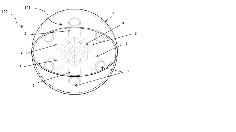
Further, each of the plurality of rods (1, 2, 3, 4, 5 and 6) is provided with a provision (12) of hemispherical shape at their free ends. These provisions (12) are provided to accommodate a roller for free movement of the rod structure (101) within the enclosure (8) ( shown in Figure 2 ). The rollers (7) are spherical in shape. Rollers are positioned partially in and partially out of the provisions. It is placed in such a way that, a portion of the roller (7) resides in a provision (12), and the remaining portion of the roller (7) protrudes outside each of the rods (1, 2, 3, 4, 5 and 6). The diameter of each roller will be less than or equal to the diameter of each rod. The rollers are fitted in a manner uniform to the tips of all six rods.
The rollers (7) are disposed in the provisions (12) such that the rollers (7) are free to rotate in any direction with respect to the force applied on the orientation indicating device (100). The rollers (7) are basically friction rollers which rotate according to the direction of force applied to the orientation indicating device (100).
Further, the diameter of the roller is smaller than the diameter of the provision (12) to facilitate free movement of the rollers. In addition, the rollers are placed in the provisions such that the center of each roller is equidistant from the center of the rod structure (101).
The rod structure (101) may be enclosed in an enclosure (8) and can freely rotate within the enclosure (8) on the application of directional force acting on the orientation indicating device (100)
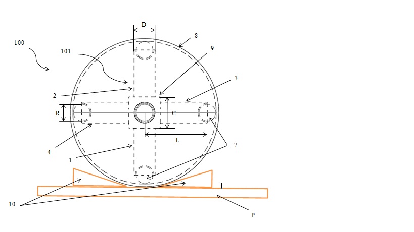
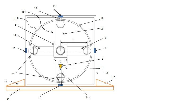
Figures 3 illustrates the front view of the orientation indicating device (100) which is fixed on a platform to determine the orientation of the platform.
The entire orientation indication device (100) is firmly fixed onto a platform (P) for which the orientation has to be determined along the three mutually perpendicular axes (pitch, roll, and yaw) X, Y, Z axes. Further, a plurality of stoppers (10) will be provided on the platform (P) to firmly fix the orientation indicating device (100). The platform (P) can be inclined at an angle with respect to the horizon. Even if the enclosure (8) is inclined at an angle with respect to the platform (P), the rod structure (101) having the heavier rod (1) always points towards gravity.
Based on the directional forces applied on the platform (P) the orientation indicating device (100) orients itself towards gravity due to the provision of the heavier rod (1) in comparison with the other rods (2, 3, 4, 5 and 6). Thereby indicates the orientation of the object.
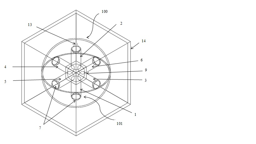
Figure 4 illustrates a perspective view of the orientation indicating device (100) configured with central cube structure inside the housing (14) for determining the orientation of the object.
The enclosure (8) may be fixed to an inner surface of the housing (14) with the aid of a fixing arms (13). The housing (14) in the present version is a cuboid having equal dimensions.
Figures 5 illustrates front views of the orientation indicating device (100) depicted as an orientation sensor embodiment.
The housing (14) is mounted on to a platform (P), the housing (14) is held in place by a plurality of stoppers (10). Each face of the housing (14) is equipped with sensors (15) such as CCD image sensors, optical sensors or CMOS sensors. The heavier rod (1) is equipped with a light source (S).
The light source (S) continuously emits a light beam (LB) during the operation of the orientation indicating device (100). When the platform (P) is moved at an angle ɵ, the entire housing (14) displaces according to angle ɵ. The heavier rod (1) which is equipped with the light source (S) displaces in the direction of the gravitational pull. This deviation in angle ɵ with respect to the orientation of the heavier rod (1) can be used to determine the orientation of the platform (P). When the heavier rod (1) is displaced the light beam (LB) activates the corresponding sensor (15) based on the displacement of the heavier rod. For example, if the platform (P) is tilted at angle 90 degree in X-axis the heavier rod (1) activates the sensor (15) which corresponds to the 90-degree angle in X-axis thus determining the orientation.
These signals can be converted into a digital reading that gives the orientation of the platform (about an axis/axes) corresponding to that signal.
Attached files:
Patents:
US 96,645,122 issued 2017-05-30 [MORE INFO]
Type of Offer: Sale
« More Engineering Patents
« More Sensors Patents