Seeking High Voltage Power Supply
Status: Search Completed
$2,000 referral fee for each accepted lead.
An accepted lead is a lead that the client decides to follow up on.
$2,000 referral fee for each accepted lead.
An accepted lead is a lead that the client decides to follow up on.
A client is seeking a power supply designer/developer that can, in the short term (6-8 weeks), provide 5-10 units of the specified power supply configuration intended for a proprietary high power based application.
- Units can be off-the-shelf, with some level of modifications if necessary.
- Units can be designed and assembled utilizing existing components in the market.
- Units can be built to the existing prototype design configuration/specifications.
Must Haves
- High voltage output (15-30 kV) in "open circuit" condition
- Controlled voltage output (“current source” behavior) of 2-4 kV in “closed circuit” conditions
- Maximum operating power: 3 kW
- Frequency range: 20-80 kHz
Nice to Haves
- Efficiency: > 85%
- Isolated voltage output from the grid
- Compact size
- Outdoor use compatibility (in enclosure)
- Shock/vibration resistant
- Safety agency listed (UL, ETL, TUV, etc)
- Non-proprietary
- Commercially available at high volume
Specifications
This power source must be able to produce a high voltage output in "open circuit" condition, (in the order of 15 KV – 30 KV). The power source must then also show a “current source” behavior in the “closed circuit” condition, and regulate the output voltage in the 2 – 4 KV range.
To achieve this, we designed a 50 KHz inverter configuration with a resonant stage connected to an elevator transformer, as shown in figure 1.

Figure 1 (click on image to enlarge).
The voltage from the grid is rectified and then inverted into a 50 KHz square signal, and then connected into an L-C resonator. The output of the resonator (voltage in the capacitor) is then connected to the primary winding of the elevator transformer. The transformer has a winding relation of 1:9, and it can withstand a voltage in the primary winding of 1.5 – 1.8 KV. The resonator allows the voltage to increase in the primary “open circuit” operation, (the system is unloaded), with a resultant voltage in open circuit of more than 15 KV in the secondary winding. When the secondary is loaded it starts drawing power from the power source, and then the resonating characteristic is reduced, allowing the voltage to decrease and the current to increase. The series inductor in the resonator is then used as a current limiting impedance in the circuit (ballast). Nevertheless, the control board has its own current limiting sensor to avoid dangerous over-current operation.
Resonator Specifications
The resonator circuit uses only a capacitor and an inductor tuned to work at a frequency of 50 KHz. Inductor: The resonator inductor ordering parameters are:
- Inductance: 208 [uH]
- Maximum Current (peak, core saturation current): 15 [A]
- Operating current (nominal, RMS): 7 [A]
- Operating frequency: 50 [KHz]
- Maximum Voltage (dielectric isolation): 3 [KV]
In our case, to be able to meet those parameters we designed an inductor with:
- Inductance L= 208 [uH] @10 [KHz]
- Total air gap width = 3 [mm]
- Minimum section area = 844 [mm^2]
- Core configuration: U + I
- Windings: 1 reel with 21 turns of twisted cable (3 threads) AWG 20.
- Isolation: 1 layer of Mylar (0.5 [mm]).
- Maximum core saturation current: 15 [A]
- Nominal current: 7 [A]
Capacitor:
The resonator capacitor ordering parameters are:
- Capacitance: 0.05 [uF]
- Maximum voltage: 6 [KV].
- Non polarized, non electrolytic (ceramic, polyester or tantalium allowed).
For the capacitor we connected a 3 x series array of capacitors, each one with:
- Capacitance: 0.15 [uF]
- Maximum voltage: 3 [KV]
- Non polarized, polyester.
HV Transformer specifications.
The HV transformer ordering parameters are:
- Operating frequency: 50 [KHz]
- Maximum primary voltage: 1500 [V]
- Maximum secondary voltage: 15 [KV]
- N1/N2 : 1/10
- Nominal Power: 2 [KVA]
- It is suggested to use an oil immersed configuration, for I.E. DIALA B transformer oil.
In our case, to be able to meet those parameters we designed a transformer with:
- Core configuration: UU + UU
- Minimum section area: 1688[mm^2]
- Windings: Two reels, with layered coils: Secondary x 65 turns + Primary x 15 turns + Secondary x 65 turns (30:260).
- Primary coil: Twisted cable with 3 threads AWG 20.
- Secondary: 1 Thread AWG 20.
- Isolation: 2 layers of Mylar (0.5 mm) between layers, the transformer must be immersed in Shell Diala B transformer oil.
- Maximum core saturation voltage (primary) 1.5 KV.
- Maximum open circuit voltage (secondary), 33KV @1.48 KV (primary), measured with air arc discharge @11mm with flat electrodes.
- Operation frequency 50 KHz.
Control board and inverter specifications
To be able to create the 50 KHz square AC signal, we used a full bridge IGBT inverter. The PWM controller used, is an UC3895 from Texas Instruments, and uses a technique called "Phase shift modulation" PWM, which increases the efficiency and suppress the noise significantly compared to conventional PWM technologies. The inverter is configured as a current source controller/limiter, and it uses a Hall Effect current sensor (LEM15) which is able to sense DC and AC currents at high frequencies. The IGBTs used must be suitable to work at high speed, at least at 100 KHz in hard switching mode (WARP devices). And the inverter should be able to source at least 3 KW of power. There is a proposed circuit shown in figure 2, which we already tested and uses the UC3895 controller.
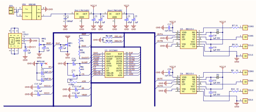
Figure 2 (click on image to enlarge).
General parameters for the inverter:
- Operating frequency: 50 KHz
- Operating Maximum power: 3 KW
- Nominal power: 2 KW
- Topology: full H Bridge, using high speed (WARP) IGBTs.
- Current limiting functionality (in the bridge DC).